Last month's newsletter discussed the length to diameter ratio of inside corner radii. We are going to explore this general topic a little further in depth this month.
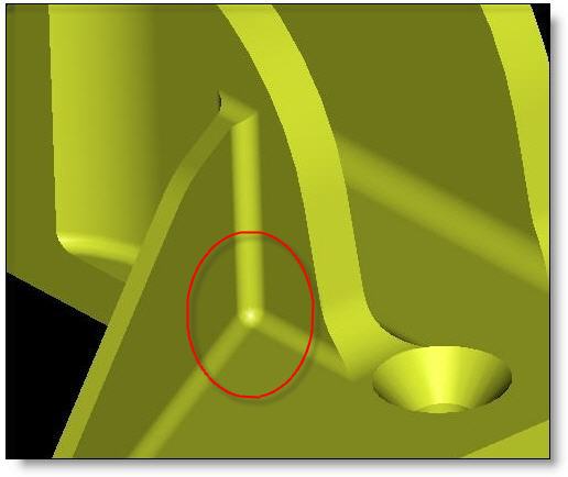
It isn’t uncommon for engineers to put a radius both on the floor and wall intersection as well as the vertical walls (see fig A). With the “apply round” or fillet feature on most 3D CAD systems, the easiest thing to do is to select both that floor intersection and the wall intersections and just apply the same size radius to all those. But in fact, what saves you a few seconds work to have just one feature, can cause enormous headaches for the machine shop and cost you a lot of money in the long run.

Fig. A: Equal floor and wall radii lead to a condition like the one in figure B.
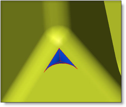
It isn’t obvious what it takes to machine the area in the corner. It is much more complicated if the floor radius is smaller than the wall radius. Because of the equal wall and floor radii, two tools must be used to clean up this area completely. The wall needs to be cut with a ball end mill (an end mill with a full radius on the tip). The floor of the part needs to be cut with a flat end mill, but this will leave a triangular shaped section in the corner that neither tool can reach. (see fig B).

Fig. B: The material in blue cannot be easily removed.
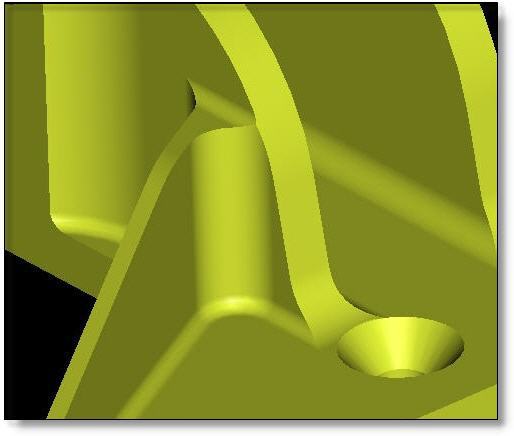
This condition can be avoided by modeling the floor radii smaller than the wall radii (see Fig. C). This enables the shop to machine this entire area with one tool that has a flat bottom but also has radii on its tips. In the last issue of Pro Tips we identified that the larger the vertical corner radii can be, the faster the tool can travel and the cheaper the part will be. Generally speaking the smaller the floor radii can be, the better, with a 0 radius being the easiest of all. In the US, tools are readily available with tip radii in .01″ increments up to .125″. And when indicating a tolerance of this floor radius on your drawing, make it as generous as possible to allow the shop greater flexibility in choosing tools.
To put it into perspective, the equal corner radii detail will easily cost 10x what the unequal corner radii detail costs. That should offer enough incentive to spend a couple extra minutes modeling the optimum radii on your part, and reap the benefits for the life of the part.

Fig. C: A larger wall than floor radius is much faster to machine.
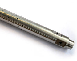
Every month we feature a really cool part that we have made recently. November’s Part of the Month is this titanium shaft. It is hard to see some of the details, but around its circumference it has a pattern of about 230 0.03″ holes and one continuous .004″ groove that zigzags around the part over 20 times from end to end. It required a very complicated 4th-axis program to execute.


