Last month’s newsletter discussed undercuts. This month we are going to talk about surface profile requirements and minimally dimensioned drawings.
The use of GD&T has increased significantly over the last several years. Engineers are being trained to use it and becoming more familiar with it. It can be a great way to specify what tolerances and features are important to your design. There is also a trend in the industry to adopt minimally dimensioned drawings and rely on the 3D model to control feature shape and location. Unfortunately, these two trends can be at odds and can add unnecessary expense to making and inspecting a part. There is no faster way to add expense than with a misused profile callout. We will explain how best to use this powerful tool.
For companies that are ISO-9001 or AS9100 certified – or really any company with a comprehensive quality system – if a customer specifies a quality requirement, then the manufacturer must guarantee that the requirements have been met. This is the crux of the problem with a profile callout; it adds a requirement for all surfaces specified to be guaranteed to the profile tolerance. Typically, only a few surfaces are very critical to the function of a part and the rest are much less important. If you are creating a minimally dimensioned drawing, you want the less signifcant surfaces to be controlled by the model. This process describes the intended purpose of a minimally dimensioned print; you will spend less time making your drawing when compared to a fully dimensioned drawing and it should take the manufacturer less time to inspect the drawing which directly reduces part cost. However, if you dimension the few items you care about and then specify a callout like the one in Figure A what you have actually done is increase the inspection requirement by an order of magnitude.

Fig. A: Bad use of a global total surface profile callout.
There are very few cases where this requirement is needed. By specifying all undimensioned features you are specifying every radius, every chamfer, every hole diameter – truly every surface on the entire part. Ensuring that all those features are within 0.005″ is very expensive to manufacture and measure. It is reasonable to think that with modern CNC machines and CAM programs this requirement would be easy to meet, but it is not. While it is true that the part will be programmed from the 3D model and modern CNC machines are very accurate there are always obstacles to perfection. Even if the entire part is manufactured within 0.005″, the work is only half done. The rest of it is proving the manufacturing, either with hours of manual measurement or hours spent programming a CMM to check the part.
The key to solving this problem is to not use a numerical value with your callout (for example, see Figure B). It is the numerical value – no matter what the value is – that is the cost driver. Even if you specified that all undimensioned features only needed to be within 0.05″, it still needs to be proven. The reality is that the part will be programmed to the 3D model, and that the part will be very close to the modeled and programmed size; probably well within 0.005″ in many cases. If that assurance isn’t good enough for any given feaure, then you should specify a specific tolerance for that feature. And if you cannot trust your manufacturer to remain accurate and precise without a numerical value, then you probably need a new manufacturer.

Fig. B: Good use of how to control undimensioned features.
As mentioned above, when you truly do need to control the profile of a given feature, then make sure you use a profile callout such as:
![]()
This type of GD&T not only controls the profile of the feaure, but with the addition of the datums it also controls the location of the feature to the same tolerance. The addition of the datums can be appropriate if needed, but can also drive cost. Particularly with large and flexible parts, you may consider adding a note about checking the profile in a restrained condition. This may make the inspection significantly easier than in a free state. An alternate method for controlling the profile shape of a feature but allowing more leeway on location is with a compound profile callout such as:
![]()
this will allow .010″ locational tolerance to the datums but only .003 on the shape of the feature.
We hope this issue has given you some good suggestions on how to keep the cost of making and inspecting your parts to a minimum. Few companies these days can afford to add cost to their product without adding value.
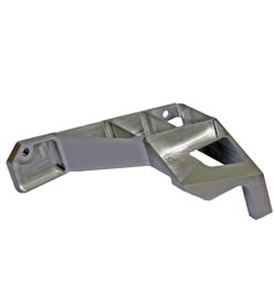
Every month we feature a really cool part that we have made recently. May’s Part of the Month is small structural aerospace part. With 0.020″ [0.5mm] wall thicknesses and several operations from multiple sides, it required careful fixturing to ensure that the tolerances could be held and that the very thin walls did not vibrate and cause a poor surface finish.


