Last month’s newsletter was about OD threads. This month we are going to talk about title block tolerances.
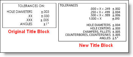
We discussed title block tolerances in September 2010 but a recent email from a customer made us realize that there is much more to talk about. Our customer proposed completely overhauling their title block tolerances for all drawings to make their parts easier to machine and give the shop more tolerance to work with. You can see in figure A the original and the new title block. The first impression is that there is a lot more to keep track of with the new one. It seems it should be easier for the engineer to not have to think about what tolerances to apply to specific dimensions, but it puts more of a burden on the shop and actually makes most dimensions tighter – with the exception of linear dimensions over 1.000. We wonder why they would feel the need to change this for all their drawings.

Figure A: Original vs New Tolerance Block.
Here is a list of specific challenges with this proposed change:
– Just because a dimension is small (under .249) doesn’t necessarily mean it is easier to make to a higher tolerance – in this case +-.002″. Imagine it was a thin web that was created by two different operations with a manual part flip between them. This web may only be a lightening pocket with no real importance, yet the shop now has to hold it with less than 50% of the tolerance it once had (assuming it was +-.005″ before).
– All holes, regardless of size are now +-.004″, again imagine some larger lightening holes or clearance holes for a fastener. Although holes are generally easy to hold to a higher tolerance, it may be unnecessary and there is an additional inspection burden now required.
– Hole centers are very tight at +-.003″ which may or may not be necessary depending on the application.
– Fillets and chamfers rarely if ever need to be as tight as +-.005″. They are generally cosmetic or non-critical features to make the part look nicer or feel nicer in the hand on outside corners, and on inside corners they are generally designed to fit a reasonable endmill size.
– Angles are now half the tolerance that they used to be. Is it really the case that when a 45 degree chamfer is machined, that we need to ensure the angle is within .5 of a degree? It seems possibly over engineered.
– Counterbores and Countersinks are generally to ensure that a cap head or flathead screw is flush to the surface. Rarely does that require proof of being within .005″. Our previous newsletter about countersinks makes note of the fact that to hold a .005″ tolerance on the diameter of a 90 degree countersink, one would need to hold the depth at .0025″ which is likely not what the engineer had in mind.
One question we like to have engineers ask themselves goes something like this: “If I specify a .005″ tolerance on this dimension, and a part comes in with a .007″ tolerance, would I reject that part as bad and ask the shop to remake it?” Sometimes for critical dimensions, the answer is an unequivocal yes. But many times the answer is a definite no. And if the answer is no, then why specify a .005″ tolerance in the first place? And if .007″ is acceptable, than is .010 acceptable? At some point, you will hit the point of diminishing returns and the part will not get cheaper as you make the tolerance lower. But generally, there are lots of dimensions on drawings which have not hit that threshold and there is still cost savings to be had. Talk to your shop about this, only with a good dialog will you distill the facts down to the least costly design which still meets your needs.
So please for the sake of your company, for the sake of your suppliers, and for the sake of US manufacturing competitiveness, make sure your changes are necessary and help to remove cost and waste from the value stream.


