Last month’s newsletter discussed a broad overview of DFMA in the supply chain and presented a white paper on the topic. This month we are going to talk about surface roughness on machined parts and how that affects cost. This is the second topic suggested by Larry V. at Lockheed Martin – thank you Larry! Let’s hear some more topics from the rest of you. We can’t let Larry get too far ahead.
Before we get into this month’s newsletter, please visit our new website page for our DFM Bootcamps. Our recent bootcamp at NASA was extremely successful and we are scheduling more around the country. For qualified companies the bootcamp may be offered at no cost, which makes the ROI really really good!!
Some engineers don’t often spend time thinking of surface roughness unless they have a very specific need for a sealing surface, a wear surface, or some other specific need. Very often we see the surface roughness called out on the title block of the drawing as a global requirement, with little thought given to which surfaces it should apply. Depending on the type of cutting condition, the surface roughness requirement may have a large effect on the machine cutting time and therefore the cost. There is an opportunity to save costs by not specifying surface finishes which may be hard to achieve. But how do you know which finishes are hard to achieve? Hopefully we’ll shed some light on that here.
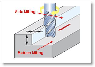
Different types of cutting tools will leave different finishes and levels of roughness. An endmill will leave a different type of finish on the bottom floor than it will on the side (see Fig A). A face mill will leave a different type of finish than a ball mill surfacing a complex shape. A turned part will have a different type of finish on it’s turned OD vs. a drilled hole down its center. Similarly, the same tool will leave different levels of roughness depending on the cutting feedrate, spindle speed and depth of cut. At its most basic, the faster a tool is feeding the highter and wider the scallops will be between each cutting edge as it passes by a certain point. (This newsletter won’t get into the definition of surface roughness or how it’s measured and nuances of both. That is a very large topic. For a good basic definition of surface roughness see Wikipedia.)

Figure A: Side Milling vs. Bottom Milling.
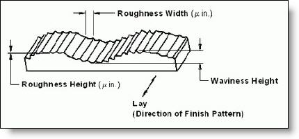
The larger the scallops are, the rougher the finish will be. These scallops are the machining marks called Roughness as shown in Figure B. For a given RPM, the faster the feedrate becomes, the wider and higher the scallops will be. The lay of the marks will be determined by the type of cutting condition – side milling, bottom-milling, etc. The waviness is affected more by loose spindle bearings, deflection, vibration in the system, or other factors. Waviness is generally not visible unless it is really severe.

Figure B: Diagram of surface roughness and waviness.
The general range of surface roughness that we see called out on most applications for machined parts is between 125 and 16 Ra(Roughness Average) µ” or microinches (3.2 to .4 µm) for milled parts and down to 8 µ” (.2 µm) Ra for turned parts. A 125 finish is easily achieved with virtually any feed/speed combination using bottom or sidemilling. Only the cutting operation of surfacing a lofted surface with a ball end mill would possibly leave a roughness more than 125 µ”. So if your part doesn’t have lofted surfaces, it will not drive any cost at all to call out a 125 µ”. In our experience, with a good solid machine, and using appropriate feeds and speeds, a 32 µ” finish shouldn’t be much of a burden or drive much cost. A 16 or even an 8 µ” finish is possible with sidemilling , but it requires an ideal set-up with a very rigid machine, very slow feedrates and sharp endmills. Floor finishes in this range can be achieved as well with facemills that have special wiper inserts which almost burnish the floor as they travel. Turned parts can be made down to a 4 µ” finish – but again, only with an ideal set-up in some materials. Expect to pay a lot for that requirement. That said, if you have a part where the finish isn’t really a factor in it’s function or appearance, then we recommend calling out no lower than a 64 µ” finish as a general note. Unless you really really don’t care, and the overall length and width of your part could be cut with a band saw – in which case leave a loose dimensional tolerance and no surface roughness tolerance at all. We rarely see parts where this would be tolerated, but if you have them, then cut the cost by removing the requirement.
If you have lofted surfaces which require surfacing or stitching with a ball mill, then those surfaces are a different story. Without requiring handwork, the finer the roughness, the longer the machine time will be. This is because the step-over value used for the ball mill will directly affect the surface roughness. A very handy calculator can be found on our website here. Of course with hand finishing you can make a lofted surface very nice looking and remove all the machining marks. It just costs a lot.
For turned parts, the nose radius of the tool will have one of the largest effects on the surface roughness as you can see from the calculator on our site found here. So if you have an inside corner radius on the OD or ID of your part, allow the largest radius you can. It will give the programmer the option of using a larger radius on the tool which can drastically cut the machining time and your cost.
One common mistake we see often is engineers trying to use surface roughness as a way of indicating that they want a cosmetic surface. Cosmetics and roughness have little to do with each other so please don’t make this mistake. A surface with a very low roughness average can still have lots of scratches, blemishes, dings and just plain look bad. This is partly because the measurement of surface finish is an average and scratches may not affect the number enough. In another example we have one customer for whom we machine aerospace cockpit panels. They require a very cosmetic part so they indicate a 32 µ” finish. They also asked for the parts to have a bead blasted finish so their paint has better adhesion. But the bead blasted finish they specify measures out to be over 100 µ”, over 3x the tolerance they say they allow. In this case the cosmetic blasted finish is far more important than the roughness average. If cosmetics are what is important to you, then don’t use surface finish roughness to achieve it. It isn’t guaranteed to get you the results you expect.
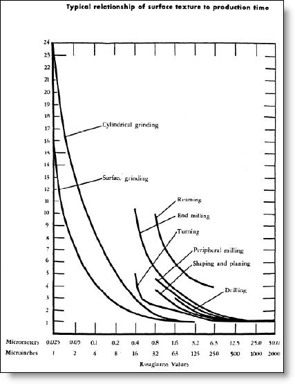
Below in Figure C is a chart which shows the time required to machine various levels of surface roughness with different processes. Don’t pay particular attention to the actual time numbers, just look at the slope of the curves which give you an indication of the time involved as you get low on the roughness scale. If I can leave you with just one piece of advice, it would be to pay attention to your requirements. Don’t just leave it up to your company title block. Be intentional with your requirements and give the shop as much tolerance as you can allow. It will save time for them and money for you.

Figure C: Time vs. Surface Roughness.
Every month we feature a really cool part that we have made. August’s Part of the Month is a machined medical housing for a centrifuge. Machined from a solid chunk of aluminum to a very fine surface roughness (then all machining marks removed by hand) the part was then black anodized and assembled with several other components for a turn-key mechanical assembly.


