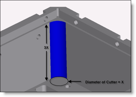
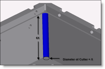
One of the single biggest cost drivers for machined parts is the length of time it takes to machine it. The rigidity and strength of the actual cutting tools often determines how much time it takes. Very simply, the shorter a tool is, the faster it can feed, and the less the part will cost to make. The selection of these cutting tools is determined by the design of the part and a few simple rules can really help reduce machining time. When designing parts that have pockets, or other features with vertical inside corners, you will need to leave a radius as the machining process uses rotating tools. Use the largest radii you can get away with. The tool that is used to machine a particular feature will obviously have a diameter of 2x the radius that you put in your model. If you design a part with a 1/8” radius, it will require a minimum of a 1/4” tool to cut that feature. The larger a tool that can be used in that corner, the faster it can feed through the material. As the length of that corner increases, the length of the tool must increase as well and that tool must be fed much more slowly to avoid deflection and breakage. The relationship is worse than linear. For every doubling in length, the feedrate is more than cut in half. A good ratio is less than 3:1. Once you get up to 4, 5, or 6 to one, the feedrates are much slower. See figures A and B. Under normal circumstances, 8:1 is the upper limit and is very slow and expensive to cut.

Fig. A: This is good! Rigid tools = Fast feedrates and cheap parts.

Fig. B: This is bad! Flexible tools = Slow feedrates and expensive parts.
By using these simple guidelines, significant savings can be achieved in the cost of your machined parts. As an example, one customer used 1500 parts per year of a complex part. We were able to shave $12 off the cost of the part by some simple changes to the radii on the part. That was an annual savings of $18,000 with just a few minutes work.
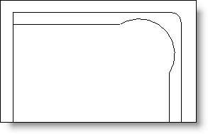
Sometimes you just need to have a long small radius because of assembly issues. There are still options to reduce the cost of features like this. Figure C shows how you can make a virtually square corner with very little intrusion into the surrounding walls. This is a great technique if for weight or assembly reasons you can’t tolerate a larger radius.

Fig. C: Virtual sharp or small corner radius
The key to this feature is to not put the center of the radius on the intersection of the inside edges. Put the center point inboard and then you can adjust it to fit your application. Use the biggest radius that fits the application as well.
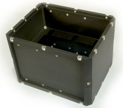
Every month we feature a really cool part that we have made recently. October’s Part of the month is (the same one used in the diagram to the left) this electronics case for a military application. About 8″ cubed and hogged out of a solid block of 6061 aluminum, this part has hard anodizing and masking of all threaded holes and counterbores. There are helicoils installed in all threaded holes, including the ones on the corners. The part was milled complete from all 10 orientations in three operations on one of our 4 axis machines.


