Last month’s newsletter was an overview of the differences between vertical and horizontal CNC mills. This month we are continuing the topic but discussing turning centers, and mill/turn machines.
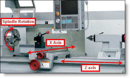
If you are designing parts that are round, or more-or-less round, there is a good chance that a turning center is the most suitable machine to make it on. The simplest type of turning center (Figure A) can only make parts that are entirely round, with all features that can be created by sweeping a cross section around a center axis 360 degrees. This is called a 2-axis CNC lathe or turning center. All lathes hold the workpiece, which is typically round (but can be square, hex or other shapes as well), in a chuck and spin it while the cutting tools are held stationary on a turret and move relative to the workpiece in the X and Z directions. Z is longitudinal along the axis of the part, and X axis is normal to the axis of the part. In the image above we can also see a tailstock which is the component on the right hand side. The tailstock can be moved into position so that it supports the end of the part being machined. The pointed tip of the tailstock is mounted on a bearing which will spin with the part and can be inserted into a center hole on the end of the part. The purpose of the tailstock is to reduce deflection of the workpiece and so as to achieve higher tolerances on the diameter and also achieve better surface finishes.
In place of a tailstock, some lathes have another spindle in the same position, which can be moved in to clamp on, or “pick off” the workpiece when all the machining is done on one end. This is called a sub-spindle. Then the sub-spindle can be retracted back and cutting tools can be used to machine the opposite end of the part. The advantage of this type of machine is the ability to machine the part complete on both ends without operator intervention. This leads to higher quality and more automation, therefore higher throughput and lower prices.

Figure A: Simple 2 Axis Turning Center.
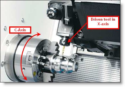
Beyond simple 2 axis turning centers, there are many configurations of multi-axis turning centers which can perform both simple turning operations, and complex milling operations as well. The most typical multi-axis turning center (Figure B) will have the ability to stop the spindle from rotating (then called a C-axis), and then have driven tools on the turret that can drill or mill side features in the X-axis, mill or drill off center in the Z-axis, or even move vertically in the Y axis. This type of multi-spindle mill/turn center can get even more complex with multiple turrets above and below the spindles and many other configurations including screw machines and Swiss-style machines. The primary advantage of a mill/turn machine is the ability to machine all of the features without operator intervention and significantly reduce the number of set-ups, and machine complex parts complete – what we like to call from “bar-to-box” – in a one-piece flow.

Figure B: Multi-Axis Turning Center.
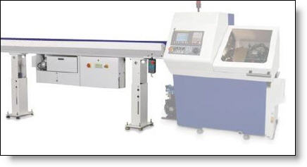
A bar feeder like the one seen below in Figure C can be added to virtually any CNC turning center which significantly increases the level of automation, therefore reducing part costs. Bar feeders can hold several bars of material and when one bar is used up, the next bar falls into place and is fed into the spindle of the lathe so the machine can keep making parts without an operator having to load more material. Lathes that can use this type of bar feeder will be limited on the size of bar which can pass through the spindle. Different sizes of machines have different sizes of through bores to accept smaller or larger sizes of material.

Figure C: Bar Feeder for Turning Center.
What machine will my parts be made on, and how can I design them to be cost effective?
This answer is a little more straightforward than last month’s question about milled parts. If your parts is only round, then a 2-axis machine will be employed. If you have a pattern of off center holes, or slots down the side, or flats for a wrench, or any other type of milled feature, then it it likely that a multi-axis mill/turn machine will be used. Or possibly a combination of a 2-axis lathe and a vertical or horizontal machining center. If your turned part has a square pocket on the side of the part, then using a machine with Y axis travel is the only option. Pro CNC has a machine with Y axis travel but relatively few machine shops do, so they would have to do those features on a CNC mill which would add complexity and cost. As far as reducing costs in the design, much of our previous advice from past newsletters applies. When designing your part size, consider the size of raw material that will be used. Make sure that the OD tolerance of the material will allow full clean up of the finished OD surface, but not require too much material to be cut away. Use appropriate significant digits on your drawings so tolerances aren’t tighter than is needed. Any inside corner on a turned part should have a corner radius. The larger you design the radius, the faster the cutting tool will be able to feed and leave a good surface finish. All outside corners should have a radius or chamfer. If you are designing parts that are long, try to accomodate a center in one end or both ends so that a tail stock can be employed to support the part while cutting. When designing threads that end at a shoulder, allow a thread relief or enough lead-out at the back end for the tool to retract without hitting the shoulder. These simple ideas will allow your turned parts to be easier to machine and cost less.
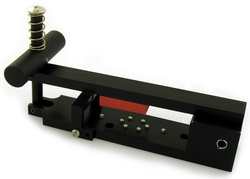
Every month we feature a really cool part that we have made. April’s Part of the Month is this assembly jig. Pro CNC’s customer needed 20 of these assembly jigs made in just over a week, with machining, plating, hardware and assembly included. Pro CNC’s dedicated prototype department and project manager pulled this off successfully of the customer.


