Last month’s newsletter discussed some ideas for making drawings simple for machining. This month we are going to revisit the topic of inside corner radii and talk about a new detail not previously discussed. This topic was suggested by Larry V. at Lockheed Martin – thank you Larry!
For many parts, the length of time it takes to machine the part is the single largest cost (more than material, plating, set-up costs). For parts like these, optimizing the cutting time is paramount to reducing the cost. Your selection of inside vertical corner radii can have a large impact on the size of endmills that can be used and consequently the speed they can be fed; this directly affects the cutting time. But the size of these radii and the diameter of the cutters can also affect the cosmetics of your part. As we discussed back in our first issue in October 2008, an optimal corner radius has a L:D ratio of 3:1 or less (see Figure A). This will allow the cutter to feed as fast as possible without much concern for deflection or tool breakage.
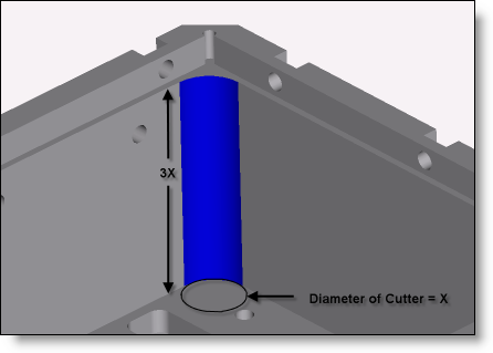
Figure A: An ideal Length:Diameter ratio for an internal corner.
What we haven’t discussed before is using a non-standard radius which is slightly larger than the cutter that is intended to be used for that pocket. In the figure above, if the radius show in blue was intended to be cut with a 1/2″ endmill, then the typical radius will be modeled at 0.25″. Back in the old days of hand cranked manual mills, this was ideal because the radius of the tool was what defined the corner radius of the pocket. The machinist would feed the endmill in one axis until they reached the size of the pocket, then would feed in the perpendicular axis away from the corner. This left a corner radius which was exactly the size of the tool. With modern CNC equipment, this is no longer necessary, let alone ideal. Because CNCs can feed on any trajectory asked of it the better solution (in general) is to model the corner which will allow both the fastest machining time and also leave the best surface finishes. We can achieve the best results for both objectives by modeling this radius at 0.26″ or 0.27″. By making the radius just a bit larger than the endmill, you will force the path of the end mill to travel around that corner with a small radius at its center line. If the radius of the corner was 0.25″ then the endmill would have to come to a full stop and turn 90 degrees with no radius. This is not only slower but makes it likely that the tool will chatter. The additional tool pressure with 90 degrees of its circumference engaged in the material causes this condition. See Figures B and C which show the difference in the centerline path of the cutter and the corresponding engagement. (The difference in radii is exaggerated to demonstrate the point.)
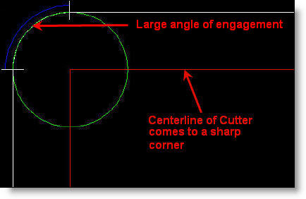
Figure B: Equal Radii to cutter and high engagement.
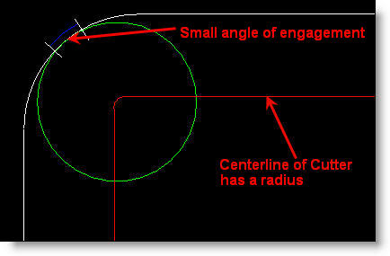
Figure C: Larger Radii than cutter and low engagement.
Chatter is caused by the endmill actually vibrating and gouging slightly into the finished wall of the part. It doesn’t look good (see figure D) and also can reduce the life of the endmill. It can be minimized or sometimes eliminated altogether but only through tweaking of feeds and speeds of the endmill. This generally leads to significantly reducing the values which adds cost to the part in cutting time and in labor to troubleshoot the problem. Machinists who care about their workmanship never want to leave chatter on a part and will try their best to eliminate it – spending valuable time which is costly. Trying to adhere to the lowest L:D ratio will also help to eliminate chatter on your parts as a shorter and stiffer endmill will chatter less.
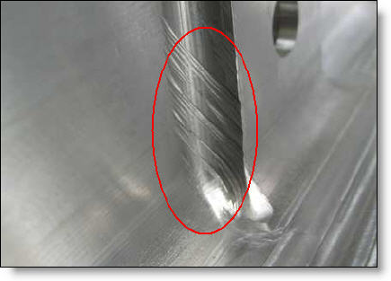
Figure D: Chatter caused by endmill and part having equal radii.
By modeling the radius larger than the endmill (we suggest 0.01″ to 0.03″ larger) you will have a part which looks better, is faster to machine, and costs less. You will also have a happier machinist…which is always a good thing.
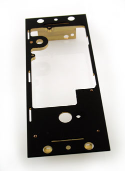
Every month we feature a really cool part that we have made. June’s Part of the Month is a small aerospace cockpit panel. With intricate details and fine masking for the black paint, this part is very finicky as are the quality requirements of our customer.
