The last newsletter was about composite GTOLs. This time we are going to talk about mating parts.
There are very few parts which don’t mate to anything. Usually parts will either bolt together, press together, slip together, sit inside of each other, or have some sort of relationship that requires the sizes and tolerances of the mating parts to be considered as a pair, or an entire set of parts. Figuring out the relationships of all these interfaces and how that relates to tolerances and nominal sizes can be very challenging.
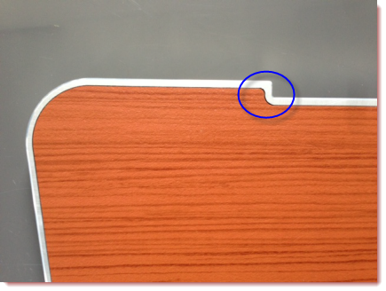
We very recently were using our new laser to make a laser cut decorative inlay for a first class aircraft food tray table (Fig A). The inlay sat in a shallow pocket machined into the aluminum table and had a requirement of being a very nice tight fit after the powder coating was applied to the table. So the design had to accommodate both the tolerances of the inlay, the pocket of the table, and also the thickness of the powder coating of the aluminum table. When the first attempt at cutting revealed some larger gaps in some areas than in others, it was determined that the inlay was not designed as a simple offset edge from the table, but rather had varying gaps in the modeled design for some unexplained reason. In addition it was discovered that the pocket in the aluminum table did not have any controlling dimensions on the drawing. It was left as undimensioned and controlled by the 3D model. Normally this would be fine for a non-critical pocket, but this one had the requirement of mating perfectly with the inlay so that there was a consistent and very small gap. (Those first class passengers are very discerning you know.) After working through this with the customer, they decided to redesign the inlay to be a consistent offset to the table pocket, and to also add some controlling dimensions and appropriate tolerances to the table so the perfect fit could always be achieved.

Figure A: Inlay not mating perfectly
Earlier the same day, I met with another customer who was designing an assembly where one part slid into another. The tolerance scheme allowed the parts to potentially be a .000″ fit when they needed it to always slide freely. They should have been toleranced so that there was never any chance of an interference (and a .000″ fit would be interference for sure). We caught it at the drawing review stage so the change cost nothing more than a couple minutes of work. Had the drawings gotten released like that and the parts been made at the edge of tolerance, it could have been a costly rework and compromised the schedule.
So it seems obvious to say, but give those relationships between your mating parts a little extra attention next time. Think of the full range of possibilities of how they might be made, and if the tolerances moved within the range how that would affect your design. It is possible you may head off some expensive rework or scrap parts.


