The last newsletter was about composite GTOLs. This time we are going to talk about engraving machined parts. It may not be applicable to all industries but I believe there are enough of you who may deal with this that it is a worthwhile newsletter topic.
We often will receive drawings with the requirement to machine engrave some text onto one of the surfaces. It could be as simple as a part number strictly for identification, or it could be cosmetic text for the end user to see such as instructions on a food tray table lift handle, or text on a cockpit display panel. Sometimes this text is intended to be filled with a contrasting color of paint, and sometimes it is not filled. Regardless of the end need, there are some important points to consider from a machinability perspective to ensure you get what you need in a cost effective manner.
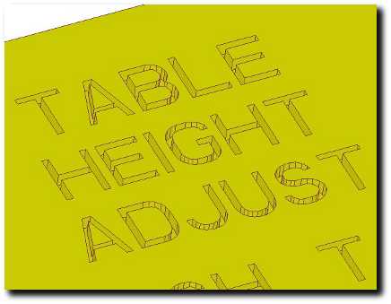
One of the biggest issues that we see is engraving that has sharp inside corners. As I am sure all of our long time subscribers know, machining can’t produce sharp inside corners without resorting to Electrical Discharge Machining (EDM). But often the CAD programs will produce text with sharp corners when it is created as a cut into the surface. Sometimes it is not expected by the customer that they will be sharp, and sometimes it is. When it is expected to be sharp this is often driven by the industrial designers who want a really nice clean crisp look (Figure A). The fact is that the engraving will have rounded corners equal to or greater than the radius of the cutter used. The closer to sharp the engraving must be, the more expensive it will be as the smaller tools will need to be fed very slowly.

Figure A: Expensive Engraved Text.
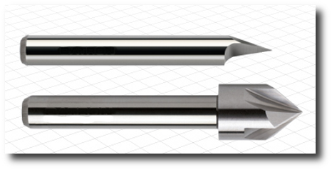
In Figure A we also can see that the walls of the letters are vertical and it would require a very small diameter flat endmill to machine the text. The Length:Diameter ratio of the endmill would require that it be fed very slowly so it didn’t break. With the amount of text on this relatively small part, the cost of engraving may well exceed the cost to machine the rest of the features on the part. This part requires ink to be filled in the engraving after it is anodized to provide a high contrast. There needs to be sufficient depth to hold the paint or ink but it would still be advisable to allow an engraving type tool (Figure B) rather than a flat endmill. The benefits of this would include being able to machine the text many times faster as the engraving tool is much stronger. With a steep included angle there should still be sufficient depth to hold the ink without the width of the lettering at the top surface getting too wide.

Figure B: Engraving Tools.
Lastly, ensure that the font you are expecting is clearly defined and communicate with your machine shop to ensure they can machine that font. If it is different what the CAD model shows it may be very difficult to achieve that font, depending on the CAM system being used to program the CNC machine.
By understanding the engraving process and talking with your manufacturer, you can ensure you don’t drive unneeded cost by asking for something that is difficult or time consuming to machine.


