Last month’s newsletter discussed countersinks and chamfers. This month we are going to discuss an unfortunate situation that was expensive and that could have been easily avoided. We hope that people can learn from our mistake. Please read this carefully to get the full effect of this situation.
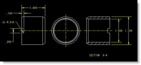
We got an order for a pretty simple part for a customer of ours. When we received the order, we received a PDF drawing of the part but not a 3D model. The drawing below in Figure A shows exactly how the drawing views were displayed.

Here is the process that this job went through:
- Job is planned by a manufacturing planner.
- Part is programmed. (Manually using G-Code for live tooling lathe since CAD model was not available to use a CAM system.)
- All dimensions on the drawing got dimension tag numbers as required by AS9102 and the drawing was reviewed by a second person besides the planner.
- The First Article Inspection part is set-up and machined by a senior set-up machinist. He does a complete FAI report for the part.
- An inspector did a second FAI report to verify the results of the set-up machinist.
- The entire order was machined across 3 shifts with 3 different machinists running the parts.
- An inspector performed a Final Inspection of the job and did a batch sampling of the parts per the AQL (Acceptable Quality Level) our customer specified. Everything looked great!
- Our customer (a prime defense contractor) sent a highly experienced inspector to do source inspection on-site at Pro CNC. Everything checked out OK and the parts are shipped to our customer.
- Our customer shipped the product off to their customer. Everything was inspected and received in good condition. The parts go into their product and all is well.
So to summarize that, at least 10 people reviewed the drawing, machined and/or inspected the parts and passed them off as good parts that met the print.
Three months later we got another purchase order for more of the same parts. We went through most of the same steps as above except that two different people were involved with the machining, bringing the total to 12 people that have been involved with the parts. We passed source inspection again and the parts were shipped off to our customer who in turn shipped them to their customer for the second time. But this time something else happened… our customer’s customer rejected the parts for not meeting the print. They pointed out that the part had a slot all the way through both walls of the part and it should only be through one side. Everyone involved was astonished that this mistake was missed by at least 12 people at 3 different companies.
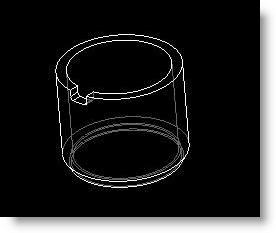
If you look closely at the drawing, there are some indications that the slot should only be through one side. The .100 dimension does not say 2x, the .032 radius only says 2x, not 4x and there is a solid line across the back of the part on the left hand view. These seem obvious in hindsight but to the 12 people involved before the mistake was caught, this was not obvious enough. So what could have been done differently to avoid this situation? Having the 3D model would have been great. The part was originally designed in Pro/E so a model did exist but the customer doesn’t always want to deliver the model. An isometric view on the drawing would have left no ambiguity at all. Something like in Figure B. There should have been hidden lines shown in the center view which would also clearly show that the slot was to be on one side only.

Fig. B: An Isometric View is very helpful in seeing what a part looks like.
The best lesson to learn from all of this is to not assume that other people will be able to pick up on the subtleties of a design if is isn’t abundantly clear on the drawing. If you are ever in doubt, err on the side of providing more information rather than less. And if possible, provide your manufacturer with a 3D CAD model if it is available.
After all, if the guys in This is Spinal Tap had provided a 3D model of the Stonehenge monument they wanted in their show, they would have ended up with the 18′ monument they wanted, not the 18″ one they got…but then the movie wouldn’t have been nearly as funny would it. If you missed the reference, please see here. 🙂
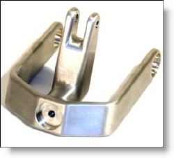
Every month we feature a really cool part that we have made. August’s Part of the Month is this interesting machined aluminum prototype for an ultrasound application. With hardly a single square corner or 90 degree angle this sculpted part was a bit tricky to fixture and had very high coaxial requirements on the two pivot holes.


