Our last newsletter was a case study about surface roughness. This month we are going to look at another case study for a part which was much more expensive than it should have been.
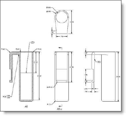
This part is a machined aluminum flower vase for an aerospace application (see fig A). It is intended to hang over a panel and hold a single flower bud or two. A nice way to greet the passengers for sure. The primary challenge with the machinability is the slot that is created between the handle and the vase body. It is quite long and skinny, requiring a tool with a 6x L:D ratio and exacerbated by the fact that the corner detail is different on each side of the slot – one side is a sharp corner and the other has a small radius. This precludes the option of using a flat endmill that is the full width of the slot, as it would remove the radius on the other side. Although not specifically dimensioned, the width of the slot is .492″, just shy of .500″ which would mean a smaller diameter tool which would be more flexible and slower.

Figure A: Machined Flower Vase.
By subtly manipulating the other dimensions, it is possible to increase the size of the slot to be larger than .500″. The diameter of the vase is .983″, the overall depth from front to back is 1.670″ and the width of the handle is .195″. By increasing the depth just .010″, reducing the diameter just .010″ the effective size of the slot increases to .512″ allowing a 1/2″ endmill to fit nicely through the slot.
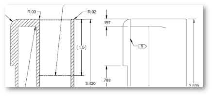
As you can see in Fig. B below, the base of the slot has a sharp corner on one side and a .040″ radius on the other. It is likely that the panel which the flower pot hangs over has the same radius on both sides, so if the .040″ radius was allowed on both sides, it wouldn’t interfere with the panel and would allow a radiused endmill to machine the slot complete. Otherwise you must use two different endmills and the flat one has to be at least .040″ narrower which increases the L:D ratio.

Figure B: Slot detail has different radii on each side.
If you look at the cross section in figure A, you will see that the inside hole of the vase has a flat bottom. While this does result in the lightest weight, it is more expensive to produce than leaving a drill tip at the bottom. A drill tip would only leave a few grams of weight and make the hole quite a bit less expensive.
The last item of note, is that this is clearly going to be a highly cosmetic part, very visible to everyone who enters the cabin. Yet the drawing did not reference our customer’s cosmetic guidelines document. Their document is very well written, classifying parts into A, B and C classes. It describes the acceptable criteria for a class A part and makes it much easier for both the manufacturer and the customers receiving inspectors to all be on the same page. We were told that the drawing was copied from an older drawing which didn’t include their relatively new cosmetic guidelines. All the great work they put into their cosmetic standard wouldn’t help in this case if it wasn’t referenced. This is a discipline and housekeeping item in this case.
When you include all the items which could potentially be improved, we believe there is nearly a 20% cost savings to be had. Not bad when the customer wouldn’t be able to perceive any differences when they walk into that cabin.
We welcome your comments below

Happy Halloween Everyone!
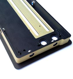
Every month we feature a really cool part that we have made. October’s Part of the Month is a bezel used in a Blue Ray player for a In-Flight-Entertainment system for an aerospace application. The part has both chem film and anodizing with some intricate masking, and hardware installed.


