Our last newsletter was about designing and machining thin wall sections. This month we are going to continue that theme by suggestion of Larry V. from Lockheed Martin and discuss designing and machining thin floors.
As with designing thin walls, sometimes it is desirable to design a floor of a pocket, shelf or web to be as thin as possible to reduce the weight of your part. Similar to walls, there is no hard or fast rule about how thin you can design a floor section. The factors include the size and shape of the floor, if there are any protrusions to help stiffen the floor, and how you hold your part for machining. With small sections of thin floors, you don’t need any special workholding provisions. But if sections become large, then the workholding becomes the primary factor in whether or not it can be machined. Fortunately there are myriad methods of workholding that will allow very thin sections to be machined successfully.
There are a few methods for holding very thin parts for machining:
- Double Sided Tape
- Vacuum Workholding (3 different methods)
- Icing Plates
- Magnetic Chuck (for steel parts)
Double sided tape is very fast and easy to set-up and use. It is very strong so holds material quite effectively. It is an excellent method to use for prototyping where only a few parts are being machined. The primary problem is that it takes a long time to remove the finished part and re-apply new tape to the new part. With two sets of fixtures it is possible to reduce the spindle down-time by changing the part out of the machine, but it is still very labor intensive to change parts out, so it is not ideal for medium to higher volume production.
Vacuum workholding is more complicated than tape and the fixtures are more expensive, but has the advantage of being very fast to hold and release your parts. With the flip of a switch, you can firmly hold down your part to a vacuum fixture and it is just as quick to release it. One potential downside to vacuum is that vacuum isn’t that strong. With a theoretical maximum of 14.7 PSI, the clamping force that can be generated isn’t as high as mechanical workholding methods. Parts may also have a tendency to slide on the fixture if some other method of constraining the part in the X and Y direction is not employed. There are two primary styles of vacuum workholding. The first uses rubber vacuum pads with a series of small suction cups (Fig A). These are a great option for parts which have larger flat sections with no protrusions from the flat surface and may be more rectangular in nature.
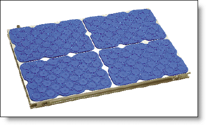
Figure A: Vacuum Pads Used for Machining.
If the shape or geometry of the part doesn’t lend itself to a vacuum pad chuck, then the second style is using a fixture with a grid pattern and an o-ring perimeter to hold the vacuum. Of these styles, there are two options. One is using a modular vacuum chuck which has a grid of o-ring grooves. Various shapes can be made by re-routing the o-ring in the grid (Fig B).
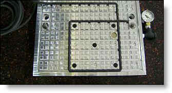
Figure B: Modular Vacuum Chuck.
The second style is a dedicated vacuum chuck with a vacuum surface designed specifically for the geometry of the part in question (Fig C). In the case of a part which the floor is not the bottom of the part, or the vacuum surface must reach up inside the part to hold the thin floor, then a custom fixture is the only practical method.
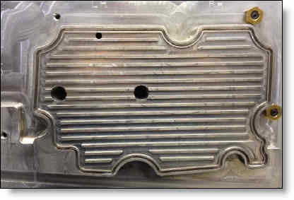
Figure C: Custom Vacuum Chuck.
As you may be able to tell in Fig C, the surface with the vacuum grid is raised above the surrounding fixture to reach inside a pocket. Because this raised boss fits inside a pocket on the part, it also holds the part from sliding during machining. The ribs on the inside of the o-ring are to support the floor so it won’t deflect away from the endmill, but the channels between them still allow for the vacuum to hold the entire surface well.
Icing plates (Fig D) are not widely used. They are expensive (several thousand for a small one) and are fairly small so can’t hold large parts. But they can hold with surprising force and are relatively quick to clamp and release. So as a niche device, they certainly have a place. We have not used them so can only report what we have read about them.
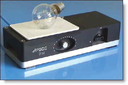
Figure D: Icing Plate.
Magnetic chucks may be a great way for holding steel parts which have flat bottoms and thin floors. They can hold with great force and can clamp and unclamp instantly. They are limited though on the variety of geometry they can hold.
So the real question is how thin can you go? In our experience, we can routinely machine floors down to .05″ in an aluminum or plastic part with a good vacuum fixture. Even with very large sections that are several inches across. There are strategies on cutting tool selection which can also aid in this. Endmills with a radius on the corners will tend to generate more downward force while cutting, possibly reducing the need for a special workholding method. There are also down-shear endmills which are ground so that the side helix helps to push down rather than pull up on the material as it cuts. With very small pockets, that are less than 1″ across, we have been able to machine floors down in the .03″ range, sometimes with normal fixtures. As material gets thinner, its tendency to warp or “oilcan” becomes greater and you are likely to have chatter or lower thickness tolerance. If you can maintain relatively small pockets – less than 10 square inches for example. And if the width of the floor doesn’t exceed an inch or two in either direction, and there is good taller geometry on the sides, then special fixturing may not be needed at all. You may be able to machine floors as thin as .125″ with no vacuum or tape needed.
As always, we recommend discussing your particular application with your shop to see what their capabilities are. And if you aren’t satisfied with the answer they give, we recommend you call us!
Every month we feature a really cool part that we have made. January’s Part of the Month is an aerospace valve assembly. This assembly has many precision components inside and is assembled and tested before delivery to the customer.
