We now have the ability for readers to leave comments at the bottom of a newsletter. We’d love to hear your comments.
Last month’s newsletter was an overview of some of the different types of tools used in the milling process. This month we are going to discuss some of the most common cutting tools used in the CNC turning process.
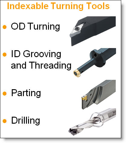
As we discussed in last months issue, cutting tools can be broadly categorized into two groups: solid tools and indexable tools. This is also the case with turning tools, although the proportion of indexable tools is significantly higher than solid tools. Nearly all modern OD (outside diameter) turning tools are indexable and only small ID (inside diameter) turning and grooving tools would typically be made from solid carbide because their size would preclude using a tool with a replaceable insert(see Fig. A). A small solid carbide boring bar can be seen here.

All of the same information that we discussed last month about coatings and materials apply to turning tools as well with different grades and coatings being used for different workpiece material types.

Figure A: Different Types of Indexable Turning Tools.
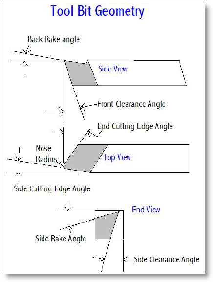
Because in turning, the workpiece spins and the tool is stationary, there is only one cutting edge and therefore the concept of flutes doesn’t apply as it does with milling tools. That said, the way the cutting edge is presented to the workpiece is vitally important and will vary depending on the type of tool and what material or type of machining operation it is designed for. Figure B shows the different terminology used to describe how a turning tool is presented to the workpieces.

Figure B: Terminology of a Turning Tool.
Tools designed for roughing or working with harder materials may have negative back or face rake angles (see lower image in Figure C) while finishing tools or tools designed for softer materials might have a positive rake angle to better shear the material off as shown in the upper image of Figure C.

Figure C: Negative vs. Positive Rake Angles.
Nearly all cutting tips have some sort of nose radius. The smaller this radius is, the more fragile the tool will be which will make it more likely to break down and need replacing frequently. Also, the slower the tool will need to be fed across the material in order to achieve a given surface finish roughness. Because as the tool feeds across the material, it leaves a spiral pattern of ridges which are larger with a faster feedrate or a smaller nose radius. Please consider the size of radius that you design into the corners of your part, and in general allow a larger radius or give a range which will allow the shop to decide the best tool to use which can lower your costs. Also do not specify a surface roughness value that is finer than you need, as that too will drive up costs. Some types of tools have what is called a wiper insert which looks like this.

These types of tools can help speed up feedrates while still allowing good finishes. A great website describing this can be found here.
If you need a sharp inside corner, or a virtually sharp inside corner, allow for an undercut on the diameter at the base of your corner. A small groove can be machined into the corner allowing a virtually sharp corner. This page shows some good pictures of how that looks and also includes a link to a catalog of styles and widths. Any width groove can be created, so design what works best for your application.
Aside from the tools described above, standard drills and reamers are used to generate holes that are on-center. If a very high tolerance bore is neaded, then the shop is more likely to use a boring bar, assuming that the length to diameter ratio is favorable. As in milling, if you require a very hight L:D ratio, this drives cost up a lot as tools will become fragile and more likely to cause chatter.
By understanding the cutting tools used in machining your parts, you can better understand what drives the cost of your parts. You can also better understand your CNC machine shop when they start talking about the tools they are using and any problems they might be having. If there is interest in getting more in-depth information about different types of tools, please let us know at the comments section of our newsletter and we will include more newsletters on this topic.
We welcome your comments below.
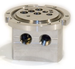
Every month we feature a really cool part that we have made. March’s Part of the Month is a stainless steel manifold. With multiple ports, o-ring grooves and threaded holes this part has requirements for high tolerances, fine finishes and excellent deburring. This is a good example of a part that can be made complete on one of our mill/turn lathes.


