The last newsletter was about the DFM process. This time we are going to talk about composite GTOLs.
Drawings are used to communicate your design intent so a manufacturer can make parts that work in your application, while hopefully eliminating extra cost that goes above and beyond your needs.
Using GD&T (Geometric Dimensioning and Tolerancing) is a great way to communicate your design intent. When applied well, they can be very specific about defining the features that you care about most and ignoring features you don’t care about. Defining the location or profile of features is one of the most important types of dimensional tolerances you can use. Sometimes you care about the relative location tolerance of a feature pattern more than you do about the absolute location tolerance. And it might be more difficult for the manufacturer to control a tight absolute location tolerance of the entire pattern, which may drive up costs. The key to communicating this requirement is to understand how to use a composite tolerance.
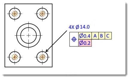
In figure A we see a pattern of holes with a positional tolerance to datums ABC (datums not shown for clarity, but assume the face and two edges). The upper portion of the composite tolerance shows us that the pattern may be out of location relative to datum ABC by as much as .4, but the lower portion indicates that the holes relative to each other may only be out of location by as much as .2. This is helpful if the mating part which bolts to this pattern of holes requires that the relative pattern is held tightly so all four holes line up with each other nicely. But for the function of the assembly, it is less critical if that pattern floats in a larger tolerance zone relative to the datums. This would help reduce cost if the process capability of machining the features was not consistent enough to hold a single tolerance of .2 for both absolute and relative location of the pattern. If all the holes were created by the CNC machine in a single workholding set-up then it is easy to achieve a very high tolerance of the relative pattern. Operator loading, or fixturing tolerances will not affect the hole pattern. But if the datums are not machined in the same operation as the hole pattern, then controlling the entire pattern to datums ABC may be more difficult and costly.

Figure A: Composite Positional Tolerance.
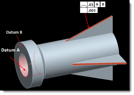
A few years ago we were trying to make similar to figure B where just a single profile tolerance of .003″ controlled both the relative and absolute profile of a set of rib features. It was very easy for us to control the relative pattern, but extremely difficult to hold the absolute pattern to the datums. When we asked our customer about it, it turned out that only the relative feature-to-feature tolerance really mattered to the customer and that pattern could float relative to the datums by quite a wide margin. Adding the composite tolerance of .01″ to loosen the pattern relative to the datums as shown was a simple way to vastly reduce the cost and complexity of making the part.

Figure B: Composite Profile Tolerance.
So when applying tolerances to your drawing, think hard about the minimum requirements of what you actually need and use the tools available to you reduce potential cost of creating those features on the shop floor. And as always, we recommend getting this feedback from your manufacture early in the process to understand how they interpret and understand your drawings. There are still far too many shops who don’t understand GTOLs well enough and may penalize you for using them at all. Making sure you, your shop and your inspectors all understand will pay dividends for you down the road.


