Last month’s newsletter discussed threads and plating. This month we are going to start a series of case studies, where we look at a part as it was originally designed, and then look at the changes that we made to make it more cost effective to machine.
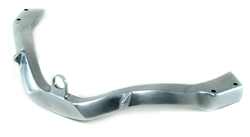
We were asked to machine this part below in Figure A. It doesn’t look that bad at first but there are lots of hidden details that were driving the cost up. The first and most obvious was its overall size. The part was designed as an aluminum casting a long time ago. The overall size really didn’t matter much, but now as a machined part it wasn’t efficiently sized to fit into a standard size of 6061-T6 bar stock. In this case, the customer had some flexibility on the overall size and we were able to change it from 2.04″ wide to 1.96″ wide, which enabled us to make it from 2″ wide bar stock rather than the 2.5″ that we would have had to use. We did not change the height as it already fit nicely into 2″ tall bar stock. This change saved about $1.00 or 25% of the material cost.

Figure A: Part as designed. Lots of room for improvement.
The next change that was made was to the pocketed interior shape. The corner radii were not designed with optimum cutting tools in mind and were both not consistent and smaller than ideal. The engineer admitted that the radii weren’t particularly important to them and could be changed. In Figure B we see the original and Figure C shows the changed radii. These changes were made throughout the entire pocket in several more places.
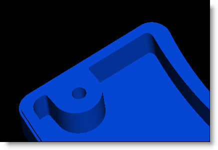
Figure B: Radii are not consistent and are too small.
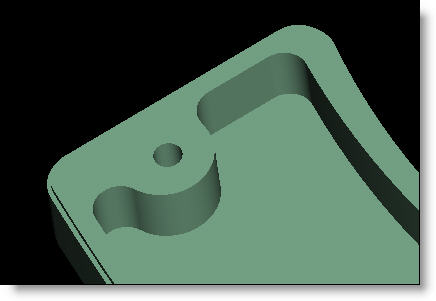
Figure C: Radii are now all the same and are faster to cut.
The changes shown in figure C represent a savings of about $1.40 in machine time savings over the original design in figure B.
The next change that was made is shown in Figures D and E. In Figure D we can see that the radii at the base of the post overlaps the radii on the outer perimeter of the part. Although not obvious why this is a problem, it is a significant cost driver.
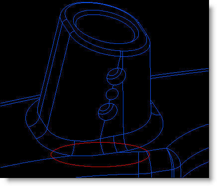
Figure D: Overlapping radii take a long time to machine.
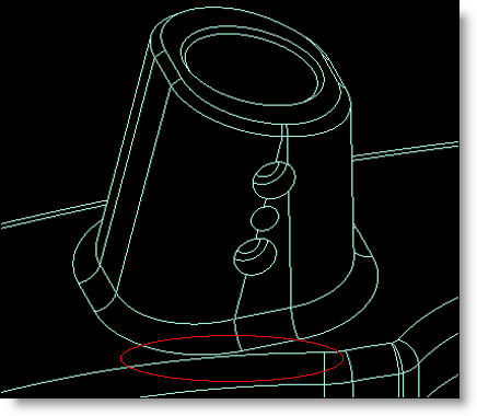
Figure E: Radii that do not overlap are very fast to cut.
The perimeter radius will be cut with a concave, corner-rounding tool. This tool has a full 90 degree arc length from vertical to horizontal so that the radius can be tangent on the top and bottom edges. When another radius intersects the upper edge as in Figure D, then the corner-rounding tool will gouge into the other radius, which is unacceptable. The only solution to this is to program the corner-rounding tool to avoid this gouge by traveling further out, and then to use a ball end mill to “stitch” the excess material which is left by machining back and forth in small steps. Our solution was to reduce the radius on the perimeter to match a standard .125″ radius which eliminated the overlap allowing the corner-rounding tool to travel past the post without gouging the other radius. The additional machine time to handle the detail in Figure D, would easily be over 1 minute compared to Figure E which would be zero extra time. So this change saved about $1.30.
Another change that was made to the part, but is not obvious from the images, is to the upper post. The angle of the post itself, and the top surface of the post both were not in even increments of 1 degree, nor were they normal to each other. We tweaked the angle of the post to be 75 degrees instead of 75.245. The top surface was also 89.5 degrees to the axis of the post which made no sense at all. We changed it to 90 degrees so programming and machining would be simpler.
Overall, the changes we made to this part saved nearly $4 to the cost of the part. Given the fact that this part was needed in a RH and LH configuration, and about 4000 parts per year of each were needed, the $32,000 savings on the first year alone seemed like a good result of the 2 hours spent.
Every month we feature a really cool part that we have made. November’s Part of the Month is not a great example of Design for Manufacturability, but it was fun to make none-the-less. This was part of a helmet-mounted heads up system for a helicopter pilot. Weight was extremely important so this was machined from multiple sides and angles so that all the material was removed from the inside. All wall thicknesses are .04″ and a .02″ sheet of 0 condition aluminum is bonded onto the back to provide stiffness to the structure. Pro CNC up with the idea of the sheet on the back when the customer discovered the part was not rigid enough.
