
Newsletter # 49 – Humility in Business
Last month’s newsletter discussed Surface Profile tolerances. This month we are going to stay on the topic of dimensional tolerance but focus on unilateral vs. bilateral tolerances.
Bilateral tolerancing (also known as symmetric tolerancing) is a method of tolerancing a dimension using equal plus and minus deviations from the nominal dimension. Unilateral tolerances (also known as asymmetric tolerances) on the other hand specify a deviation in only one direction, either plus or minus, from the specified nominal dimension. Unilateral tolerances may also take the form of plus and plus-plus, minus and minus-minus, or plus or minus some amount and plus or minus a lesser amount.
In the old days of hand cranked mills and lathes, it was quite easy for the machinist to decide on what dimension to arrive at while machining a part. If a customer specified a dimension with a unilateral tolerance such as: 2.500″ + 0.000/ – 0.010″ the machinist would either shoot for 2.495″ (the safest place to be – in the middle of the tolerance range) or if he was a nice guy would shoot for 2.499″ in an attempt to get as close to the dimension the engineer specified. There was more risk in being close to the limit but with a good machine and a skilled machinist the level of risk was low. I’m sure you are thinking at this point that with modern CNC machines it should be even easier to achieve whatever dimension the engineer desires. In some regards this is true. We can “comp” (use cutter compensation) a CNC machine 0.0005″ one way or the other and it will do it handily. But the real difficulty with unilateral tolerances lies in the programming of the part. Nearly all CNC machines these days are programmed from a 3D CAD model using CAM software. The programmer chooses edges or surfaces on the model to drive toolpaths. Figure A shows a basic rectangle with one side having a bilateral tolerance and the other having a unilateral tolerance.

Fig. A: Part with both unilateral and bilateral tolerances.
This is a pretty common example. In this case, the easiest way to program and manufacture this part is with a profile cut from the top of the part which establishes both the 4.000″ and 2.500″ dimensions at the same time with the same cutter. The CNC program by default will drive the tool at the nominal size of the CAD model. It will create a rectangle that is 4.000″ x 2.500″. But the sides with a 2.500″ dimension will be practically out of tolerance as programmed since we cannot be on the plus side of nominal at all. And with the typical small amount of cutter deflection outward, the 2.500″ dimension will likely be out of tolerance. This makes the programming of the part take much longer as the programmer will have to compensate for this with manual adjustments to the program, adjustments to CAM parameters or a separate program with tool paths for each side. The set-up of the part on the CNC machine may also take longer if the machinist needs to apply cutter compensation in order to bring the part closer to the middle of the tolerance zone. In an extreme example, if you had a tolerance of + 0.005″/- 0.000″ on the 4.000″ dimension, it would be virtually impossible for either dimension to be in spec without major tweaking to the program. This brings up the other point about unilateral tolerances. Most CNC shops want to run the dimensions in the safest range to minimize the chance of scrap. So in the case of the part in Fig. A, they would likely try to run the 2.500″ dimension at 2.4975″ which is exactly in the middle of the + 0.000″/ – 0.005″ range. This somewhat defeats the purpose of specifying a unilateral tolerance in the first place. It would be easier for everyone involved if the engineer put a symmetric bilateral tolerance at 2.500″ or 2.497″ because more than likely it is what will be delivered anyway.
The issue of unilateral tolerances is not as much of an issue with holes (see Figure B). Very often it is more critical to be able to hold odd tolerances on holes to achieve proper slip, or press fits, etc. Because most holes are machined with drills or reamers the same problem with programming does not exist. The size of the hole will be established with the tool, not the program. So if you need a .2500″ hole for a press fit for a 1/4″ pin then the shop will select the exact size reamer needed. In the case of an odd sized hole that doesn’t match a common drill size or reamer size, the problem may exist to a small degree. A hole such as that can be programmed with a circular interpolation using a smaller endmill to create a larger hole. Since that is more of a “stand alone” type of feature, the parameters can be more easily tweaked to achieve the desired tolerance without affecting other features on the part.
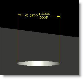
“Fig. B: Unilateral tolerances on holes are not a problem.
Armed with a bit of knowledge about which tolerance scheme is easier to machine the engineer can achieve their desired design objectives without adding cost to the product… an idea that we can all unilaterally agree is a good idea.
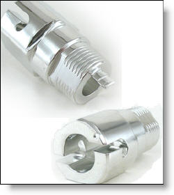
Every month we feature a really cool part that we have made recently. June’s Part of the Month is multi-axis mill-turn part used in an aerospace application. Just over 1″ long, this part made from 6061-T6 has many off-axis mill features which required the use of our 6-axis Mori Seiki NL2500 SY. This highly capable mill-turn CNC machine was able to machine this part complete in one operation. After machining, the part was nickel plated.
Related posts


