Last month’s newsletterdiscussed some cost drivers and details with threaded holes and threaded inserts. This month we are going to talk about two different types of plating and some strategies to make those finishes more successful and cost effective.
Chemical Conversion Coating
In reference to coating aluminum, this process is known by many common names – chem film, Iridite, Alodine, conversion coat or chromate. Chemical films are gelatinous films used to provide corrosion protection to aluminum alloys. The coating also improves adhesion of subsequent coatings such as paint and powdercoat. They are typically either clear/colorless or gold and yellow with a tint of brown. It is important to note that different material alloys may appear different in color when processed identically. It is not generally considered a cosmetic process as color can vary. The distinction between clear and colored may be specified on the drawing, but colored will be used by default. Chem film is a cost effective substitute for anodizing when abrasion resistance is not needed; it also has the benefit of maintaining electrical conductivity which anodizing will not.
The military specification (also used commercially) for this plating process is MIL-DTL-5541F. MIL-DTL was introduced in 2006 and superseded MIL-C-5541E which was the standard for many years. Although MIL-C is obsolete, it is still commonly specified on drawings today (Yes, I’m talking to you). There are two classes, 1A and 3. Class 1A is thicker and provides maximum corrosion protection but has greater electrical resistance; it is generally darker in color. Class 3 is thinner, providing less corrosion protection but has better electrical conductivity. The new MIL-DTL spec has introduced Types I and II. Type I contains hexavalent chromium which was the only option in the now obsolete MIL-C spec. Type II contains no hexavalent chromium which makes it compliant to RoHS, the restriction on certain hazardous substances. More plating companies are now offering Type II but it is not yet ubiquitous in the industry. If no type is specified on the drawing, then Type I is the default. Similarly, if the coating class is not specified, then Class 1A is recommended. An advantage to this coating type compared to anodizing is that it can be repaired with an approved touch-up method. Per the MIL spec, up to 5% of the surface may be touched up unless the contract states it can be more or less. Unless your application has zero margin for error, it is prudent to allow the use of a touch-up method because chem film is relatively easy to scratch, especially if there are assembly processes after plating. The touch up methods still provide a very good level of protection.
Chem film does not add any measurable thickness so in most applications provisions for plating thickness do not need to be taken into account at the design or machining stages. The pricing for chem film is significantly cheaper than anodize on a per-part basis – typically about 60% less, but minimum lot charges will apply and generally vary from $60 to $120.
Anodizing
Anodizing is an electrolytic process which converts the outer surface of metals to an oxide layer, protecting the underlying metal from corrosion. It is most commonly used on aluminum but can be used on some other non-ferrous metals. The two most common types controlled by MIL-A-8625A, are Type II and Type III. Both types are called sulfuric anodizing with the thickness being the primary differences.
Type II is considered cosmetic anodize and can vary in thickness from .00007 to .001″ (1.8 ?m to 25 ?m) with .0003″ being an average (+-.0002″ tolerance). It can be clear (Class 1) or colored (Class 2). If you specify Class 2 you must specify a color as well. There are a wide range of colors available with Type II Class 2 although getting close matches can be very difficult. If precise color is important, it is best controlled with boundary samples. The subjectivity of the color can often be a very challenging aspect of anodizing and can lead to significant costs and delays . Different alloys will color differently which should be considered if you have a cosmetic assembly with machined and sheetmetal parts made from different alloys for example.
Type III is also called hard anodizing. It is much thicker than Type II varying in thickness from 0.001″ to 0.006″ (25 and 150 ?m). If a thickness is not specified then the nominal thickness is to be .002″. Hard anodizing penetrates the substrate as much as it builds up and thickness includes both the buildup and the penetration. Type III hard anodizing offers significant wear resistance, scratch resistance and thermal and electrical resistance compared to cosmetic Type II. When maximum abrasion or wear resistance is needed, a final sealing step should not be used. For maximum corrosion protection a sealing process is used, and the type of sealing should be left to the plating company unless you have a specific requirement for sealing. It is interesting to note that abrasion resistance does not improve with additional thickness and will decrease above .0025″. The same color classes are used with Type III (Class 1 for clear or Class 2 for colored). Hard anodizing is not considered a cosmetic grade and most plating companies will not guarantee the color results as they will with Type II. It is possible for hard anodize to look fairly nice but it is not going to be consistently so. One additional note is that Type III “clear” is really not clear at all, and is often dark grey with shades of green.
It is prudent to specify where you would prefer to have racking marks. These marks are unavoidable and can damage close tolerance features.
There is also a Type I (and variants IB and IC) anodize called chromic anodize. It is far less common but is good for use on fatigue critical components as it is the thinnest type of anodize. It is important to note that Type II and III may significantly reduce fatigue properties, and the thicker the coating, the greater the reduction will be.
Because of the thickness associated with anodizing, care must be taken to ensure the finished part functions as needed. There are a few ways to approach this: 1) Machining features accordingly to accommodate the plating thickness expected, 2) asking for zero growth of the after-plating dimensions, or 3) masking critical areas before plating. Specifying before and after dimensions is fairly straightforward in most cases. It requires a bit more detailing on the drawing, but can take the guess work out of the process. If the tolerance range of the anodizing is tighter than the finished machined dimension needs to be then this approach can be successfully used. But if the finished part needs to have higher tolerances then masking would be better. As an example, if you have a 0.500″ hole with tolerance +-.0005″ after plating, and the thickness tolerance for Type II is +-.0002″ (which would apply to both sides of the hole), then the variability of the after-plating hole diameter would be +-.0004″. This would leave only .0001″ of tolerance for the machinist which is not really practical (read: economical). Plugging the hole is the best option unless the surface must be plated. Asking for zero-growth can also work in many cases. The plater can acid etch the parts longer before anodizing to remove material so the buildup of plating has the minimum affect on overall size but this can come at the cost of surface finish. Threads can be particularly troublesome, especially with Type III anodizing. Because the plating thickness builds up on both sides of the hole and both angles of the thread helix, the reduction in pitch diameter is close to 4x the plating thickness. Oversized taps can be used but the thickness tolerance can make it nearly impossible to achieve a thread class. If the application can tolerate no plating on the threads, then plugging them before anodize is the best option. Plugging holes and threads is relatively inexpensive while masking broad surfaces adds considerable expense, lead time, and the chance for non-conformances.
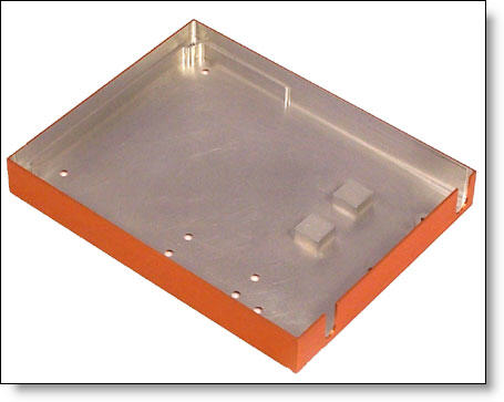
We have seen applications where a part requires both anodize and chem film on different surfaces. If you don’t ever have a need for this, count yourself lucky. This is a pretty expensive and trouble-prone option but can be successfully executed. There are two basic options to achieve this requirement: partial machining – anodizing – more machining – chem film or: machining complete – first plating process -masking – second plating process. The complexity and shape of the area with the different finish will help determine which of these applications is used. The former has advantages of no masking cost and the delineation between the plating types will be very clean and crisp. The disadvantage is longer lead time, shipping costs and an additional machine set-up. An example of such a part is seen in Fig. A. The entire outside of the part needs to be anodized for cosmetics while the inside needs to be conductive and have corrosion protection. An anodized surface will not be affected by submersion in the chem film process which is the key to allowing these processes to be used. If the area required to have chem film is relatively small and simple in shape (such as a flat grounding surface around a hole) then the most cost effective method is to mask the area, anodize the part and then chem film once the masking is removed. If your application does not require compliance to the MIL spec, then it is possible to get fairly good protection with a chem film touch up method only.

Fig. A: This part required anodize and chem film. Two stage machining was used.
It is possible to install stainless steel hardware before chem film plating but not before anodizing. Depending on the application, this may not be advisable because chemicals may be trapped between the hardware and the part and leach out at a later time. If you are concerned about this, you should specify that hardware be installed after plating. In our experience with hardware such as helicoil inserts, we have yet to see residue or leaching after the fact related to the hardware. Installing the inserts during the machining process rather than as a batch operation after plating, can save significant costs and lead time.
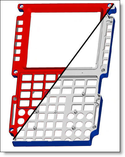
If you have a requirement for plating on certain surfaces, or even paint with masking, the most clear way to communicate it is with colored isometric views on the drawing. Most 3D CAD systems days can generate shaded full-color views on the drawing. Put a front and back view on the drawing showing which areas to mask. See Fig. B. This even works well with different levels of cosmetic requirements in different areas, such as Class A (highly cosmetic) on the front face and Class C (seldom seen) on the back.

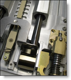
Every month we feature a really cool part that we have made recently. March’s Part of the Month isn’t a part at all. It is a Food-tray Table Assembly for a business class airline application designed by Bucher Aerospace Corp. With a BOM of over 80 part numbers and hundreds of individual components, this assembly demonstrates our significant capabilities. We also worked side-by-side with the client to refine the design and ensure that the mechanical fit and function of the assembly worked perfectly the first time.


