Last month’s newsletter discussed chemical conversion coating and anodizing. This month we are going back to geometry to talk about undercuts in machined parts.
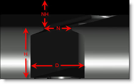
Sometimes it is impossible to avoid creating a feature that can’t be made with a standard endmill; often this means using an undercut feature. See Fig. A for an example. These features are generally more expensive because they require a custom ground tool (see Fig. B) in most cases and the cutting feeds are slower to accommodate the more fragile neck (N) diameter. Both the speed of the cutter and also the determination of whether or not the cut can even be made is based on the ratio of the cutting diameter (D) and height of cut (H) vs. the neck diameter (N) and neck height (NH). There are no hard and fast rules about what ratio of D:N is possible, let alone one that will be inexpensive to produce. Because the length of the neck (NH) is also a critical factor, as is the cut height (H), a review of the D:N ratio is insufficient in calculating difficulty and cost. When any one factor, or a combination of factors, becomes too extreme the cutter would be so fragile that the risk of breakage at any reasonable feedrate would be extremely high.

Fig. A: This image shows a feature that must be machined with an undercutting T-Slot tool.
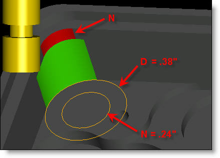
It isn’t uncommon to see an engineer specify an undercut feature that is not possible to make. The design of the undercut is such that there could be no neck diameter or it would be so small as to be impossible. There is a pretty simple way to avoid this situation. If you are modeling a feature that requires an undercut, you can sketch in both the cutting and the neck diameters as shown in Fig. B. We can see in this example, that the ratio of D:N is about 1.5:1 which is a very reasonable and inexpensive feature. You should also note the ratio between the cut height H and heck height NH are also at a reasonable ratio. The neck height is very short so the cutter will not be too fragile. (This part had much worse ratios before the customer consulted with Pro CNC). When you do this with your own part, measure and take note of these ratios to see if they seem too extreme and therefore expensive. It is also important to note that these two diameters share a common axis. That is not often the case and makes this exercise even more important in determining what the size of the cutting tool will be.

Fig. B: This part has a well designed undercut.
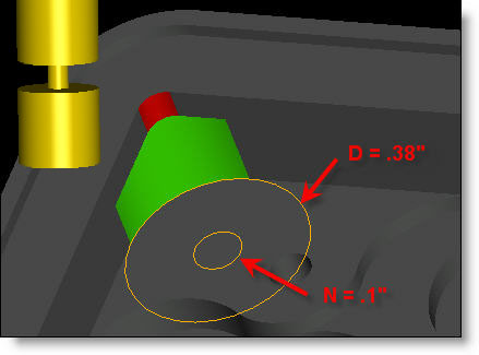
Figure C shows a poorly designed undercut and the corresponding tool that would need to be used to make the part. This design would require a tool with a 3.8:1 ratio; the tool needed would be very fragile and must be fed very slowly as the chance for breakage is very high. You may have a difficult time finding a machine shop willing to take this on or worse end up with parts that don’t meet your requirements because of an interference from the omission of the tricky undercut. At best, you will pay a great deal for undercuts that border on impossible.

Fig. C: This part has a poorly designed undercut.
By following these steps and being aware of what type of cutting tool will be needed to machine your part, you can reduce costs and frustration levels often associated with these types of features.
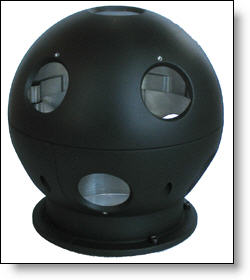
Every month we feature a really cool part that we have made recently. April’s Part of the Month is a neat set of parts we just made for a 360º spherical camera. Comprised of a top housing and two lower housings, these parts have holes on multiple angle and require a high level of cosmetics and precise tolerances..


