Our last newsletter was about title block tolerances. This month we are going to talk about Toric Joints, or more commonly known as O-rings, a form of mechanical gasket.
O-rings were originally patented in Sweden in 1896 and were not brought to the USA until 1937, when a machinist named Niels Christensen was awarded a patent for O-rings as part of a streetcar air brake system; Westinghouse ended up as the ultimate assignee of this patent. The first wide scale usage of O-rings did not happen until the US government “commandeered” the patent for use by contractors in World War II. Since then, they have grown in both popularity and applications. Unfortunately, they had a major part in history when the Space Shuttle Challenger (NASA OV-099) exploded during liftoff in 1986. The O-rings that sealed one of the solid-fuel rocket booster failed; it was determined that the wrong material had been used for the application. If an application requires use in low temperatures, high temperatures, or vacuums, it is a good idea to do some research to ensure (and insure) that the selection satisfies the application.
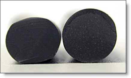
The power of O-rings is that their behavior is predictable, they are simple to manufacture, and are relatively inexpensive. They do, however, require mating parts that have specific geometry that can drive cost in some cases. The key to O-ring performance is compression; they serve as pressure bridges by maintaining a pressure difference with mechanical compression. See figure A.

Figure A: O-ring showing compression.
The two major types of geometry where O-rings are used include radial surfaces and faces. Radial surfaces are usually shafts or holes where there is some rotation. Faces are usually sealed in circumstances where a lid is fastened to a housing or two housing members are being fastened together. In either case, fluid required for lubrication and cooling is retained or the system is being protection from the environment, or both.
The ideal groove geometry really depends on how the related system is being used; a general purpose groove will work well for a static interface but for dynamic interfaces the geometry will need to depend on whether the system is being sealed against only liquids or air as well.
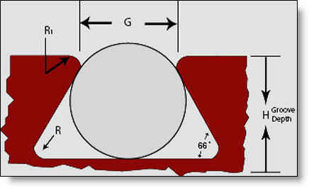
There is also some consideration needed for corner radii in the case of face surface seals. As usual, the smaller the corner radius, the smaller the cutting tool that must be used (which drives cost). Often, a dovetail as shown in figure B will be used to help retain O-rings.

Figure B: O-ring shown in a dovetail groove.
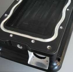
The problem is that the dovetail often requires a slow cutting speed and custom tools, as well as the awkward start/end point for the cutting tool. Instead of using a smaller corner radius to retain O-rings, we recommend using a “chicane” style of geometry. Much like the road you see below where cars are being slowed down, the chicane provides a convoluted path out of which the O-ring will have difficulty rolling and springing out of.

Figure C: O-ring chicane.
One of the more common cost drivers related to O-rings is surface finish. Groove floors and faces and walls are often mistakenly held to the same level of surface finish. For most applications (disclaimer: this is very large generalization), a floor and face surface finish of 16 RMS and wall surface finish of 32 RMS will do. Most O-ring manufacturers have specific recommendations about this. A surface that is too rough will abrade the O-ring while a surface that is too smooth will discourage lubrication of the O-ring.
On the mating part (the one without the O-ring groove) if a tight seal is desired, requiring a high surface finish, it may be best to have a step protrude above the face and specify the high surface finish on only the protruded face. If the zone mating with the O-ring is the highest area, which is the best scenario, the high surface finish can be easily lapped. In the case of turned features (either shafts or holes), a higher surface finish is easier to attain. Please see our August 2010 newsletter for more information about surface finish.
Every month we feature a really cool part that we have made. August’s Part of the Month is a housing which utilizes a wavey O-ring groove design to ensure that the O-ring stays nicely in place when assembled. The part has hard black anodizing with the O-ring groove masked and chem filmed.


