Last month’s newsletter discussed some of the issues with specifying material sizes and specs. This month we are going to discuss the topic of geometric tolerances and how they drive cost.
Nothing can drive up costs on a part more quickly than tight tolerances that are difficult to machine or measure. Some tight tolerances are not any problem at all to achieve, while others are very challenging. All too often we see drawings with poorly applied tolerances which drive up the cost of the part or worse, potentially not fitting together with its mating parts. A better understanding of the machining process will allow the engineer to specify an intelligent tolerancing scheme which serves their needs well but doesn’t needlessly drive up costs.
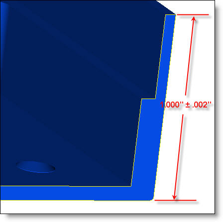
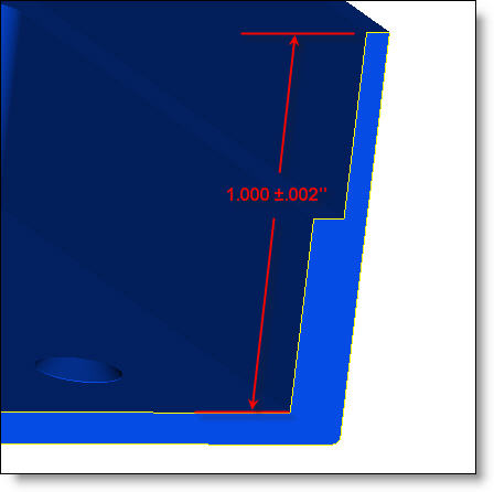
As a rule of thumb, features that are created by the machine tool capability will be relatively easy to hold to a high tolerance. On the other hand, features that are affected by operator handling and loading into subsequent fixtures will be much harder to hold at a high tolerance. An obvious example of an easy to hold tolerance is the dimension between two steps on the same side of a part as seen in Figure A. The same tool will be used on these faces and the positional accuracy of the CNC machine will be the primary contributor to variability (essentially zero). With a positional accuracy of around .0001″ [.0025mm] on an average CNC machine, this should be much tighter than most applications require. So if you need to specify a tolerance of .002″ [.05mm] this shouldn’t pose too much of a problem. Conversely, if you need to specify a high tolerance to the opposite face of the part, like in Figure B, this would be much more challenging. The reason for this is because in most cases the part will be removed from the CNC machine, manually flipped upside down and re-clamped in order for the back side to be machined. There are a lot of variables introduced with this process and a tolerance of .002″ [.05mm] would be much harder to achieve. There would likely be more complicated fixturing, longer machine set-up, longer loading times per part, and a higher scrap rate. These would all drive cost considerably.

Fig. A: Faces on the same side are easier to hold tightly.

Fig. B: Faces on opposite sides are more difficult to hold tightly.
Given the above, parts will still generally be less expensive to make when tolerances are looser. Often engineers rely on the tolerance block to help communicate their needs such as .xx = .01″ , .xxx = .005″, .xxxx = .001″ (or metric equivalent). Sticking with these general tolerances is easy to specify but may drive cost needlessly. If .005″ is too loose of a tolerance, it doesn’t mean that .001″ is the only other option. Why not specify something in the middle, such as .003″ or even .0035″. An intermediate tolerance may be much easier to achieve and subsequently less expensive. When working with smaller tolerances, a small difference can be vastly easier – .0015″ is 50% more tolerance to work with than .001″. Depending on the application, that extra .0005″ might make the difference between hitting your parts cost budget or not.
With every application there is a point of diminishing returns where loosening up the tolerance won’t lower the cost of the part. If the process employed to make the feature can easily hold the tolerance, then making it looser will not reduce price, unless it becomes loose enough that a different and less expensive process can be used. For example, a part’s tolerances could be loosened enough that it becomes feasible to use profiling technology like laser cutting, abrasive waterjet, or routing. You may also consider the option of supplying a mating part for an in-process fit check. It may also be sufficient to perform a “program check” where the programmer verifies that the feature will match the model but there is no physical verification done. Discussing specific applications with your manufacturer is the best way to determine if changes might apply in your application.
It is becoming common to apply a global profile tolerance to an entire part. While easy to specify, this may require significant inspection costs to prove. Even if a part does fall inside a profile tolerance, the manufacturer would need proof of that being the case. This would require a significant number of hand measurements or a full CMM report, either of which is costly. While profile tolerances have a real purpose, be sure you are using them effectively.
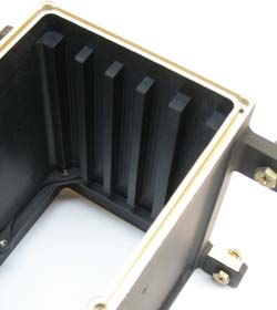
Every month we feature a really cool part that we have made recently. January’s Part of the Month is an aerospace electronics chassis. The most notable feature on this part is the card guide slots on the inside. Rather than employing an EDM machine or brazing the part from two pieces, we revived a forgotten manufacturing process from the history books. Vertical slotting was used to make these features with sharp inside corners. But rather than using an old shaping machine, we did this broaching right in the CNC machine. The result was an incredibly fast process with no additional lead time for batch processing on an EDM. This is a great example of Pro CNC’s innovative thinking.


